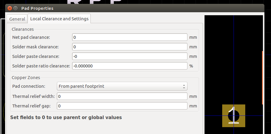
F4.6 Local clearance and settings should be set to zero
Pad clearance values are determined using a priority system, which checks the following locations for clearance values, in descending order of priority. If a particular setting reads as zero (0) then it is ignored, and the next location is checked.
-
Local pad settings - If an individual pad specifies clearance values, these are used
-
Footprint settings - If clearance values are specified in the Footprint Properties window, these are used
-
Global settings - If no values are specified as above, then the global values (as specified in PCB settings dialog) are used.
Unless there is a specific reason for setting explicit values for local clearance values for pads or pins, they should be left at zero (0).
Exceptions:
If the component datasheet calls for specific clearance values for a particular pad (or the entire footprint) then these values should be used as appropriate.
